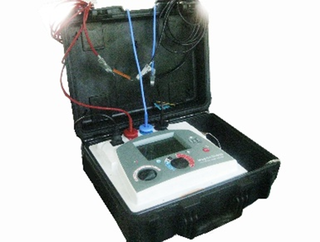
insulation tester
1. DESCRIPTION
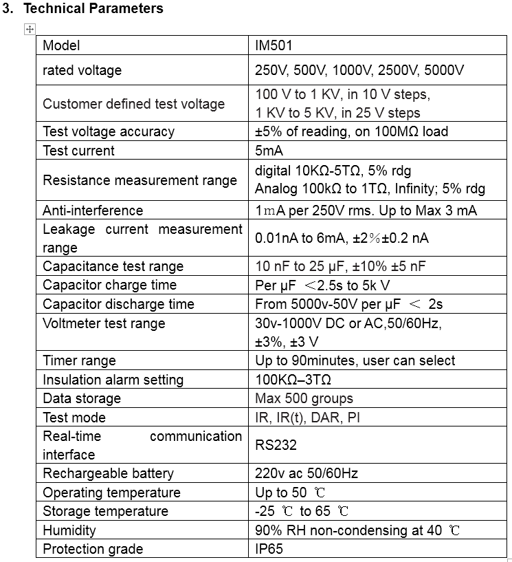
The IM501 is a compact, resistance-current measuring, data-retention, PC-communication, battery-operated instrument with a resistance test range of up to 5TΩ.The design of the instrument makes full use of microprocessor technology, uses a large-screen LCD display, and integrates digital and analog insulation resistance readings.
The rated voltage of 250V, 500V, 1000V, 2500V and 5000V can be selected.
After starting the test, the LED high voltage alarm light in front of the instrument starts flashing and displays a high voltage symbol. The timer in the instrument starts to time itself and displays the time spent on the test. A timer can set the duration of the test and automatically stop the test when set time reached.
The battery capacity is continuously displayed as a segment indicator. Charging is required when none of the segment indicators light up. Power is provided by two sealed rechargeable lead-acid batteries in parallel. If one of the two batteries fails (or the internal safety breaks), the instrument can be powered by the other battery to continue working. The battery can be charged using an external 13.5V DC power supply.
The safety design features are:
The flashing high voltage alarm LED and high voltage symbol on the front panel of the instrument remind the user of the presence of high voltage during test.
Automatically discharge the load at the end of the test.
Test terminal jack locks the test terminal in the box to prevent accidental disconnection.
Model IM501
2. FEATURES AND BENEFITS
Insulation resistance Test (R)
This method measures the insulation resistance at the selected voltage to obtain a transient resistance value.
Test Current Measurement (I)
In this way, the insulation resistance is measured at the selected voltage to obtain a transient current value.
Polarization index test (PI)
The polarization index is a term applied to the dielectric absorption ratio, when the insulation of an insulator is tested, the resistance is measured at time T1 (the default time is 1 minute) and time T2 (the default time is 10 minutes). The polarization index can be obtained by dividing the resistance value at time T2 by the resistance value at time T1. A large PI value indicates a high dielectric absorption. (See "Application of Experimental Techniques"). Final test results are provided with corresponding leakage current values and capacitance values. The test can be performed at any voltage. Users can set their own PI values according to their needs (see User defined PI Test).
Dielectric Absorption Ratio test (DAR)
DAR is the ratio of resistance measured at 60 seconds versus 30 seconds.
PI is the ratio of resistance measured at 10 minutes versus 1 minute.
When different measurement modes are selected, the corresponding ratio will be displayed at the bottom of the screen. For DAR, the ratio result is displayed after 60 seconds. For PI, the ratio result is displayed after 10 minutes.

Included Accessories
1. Power cord
2. Test lead set 3 x 3 with clips
3. Operation manual
4. Certificate of Calibration

A total of 1 page 1 data